Hardware:
Software:
Developpement:
Gallery:
|
BOB4 - Autonomous indoor helicopter UAV
Electronics
Global schematic :
|

|
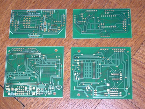
Logic board :
The electronic is spread on 2 boards. The 2 boards are directly connected together, one on the other.
Here is the board:
|


|
Use of SMT:
Using SMT components is very useful. It allow to reduce the size of the electronics, because of 2 reasons. First, the components are smaller. Second, you can mount components on 2 sides at the same time. Having compact electronic boards is essential in a small UAV. It is the only way to have a lightweight electronics.
|
Motherboard : Embedded Master (from GHI Electronics) :
This controller board works with ".net Micro Framework" from Microsoft. This is not very suitable for "real time applications". But the main advantage is that it is easy to program. It has a big RAM capacity; that is useful for making big logs in real time.
I chose this board because I wanted to be able to program complex applications. I had the Idea to make the UAV communicate via WiFi or via GPRS connection. But I will never do this...
|

|
bluetooth radio module:
Module Bluetooth Free2Move F2M03GX.
I chose these compact bluetooth modules. They have more power than normal bluetooth modules. This is reassuring to avoid losing connection.
The bluetooth module inside the drone has an integrated antenna. This makes the board even more compact. The transmitter has a real separated antenna, for a better radio link.
|

|
Hardware fail-safe:
The fail-safe is very simple. It is made with 4 AND gates (74HCT08). These gates only allow power to motors and servors if both the radio link and the motherboard (Embedded Master) allow it. The bluetooth module allow power only if the radio link is well established, and if a safety-switch has been switched-ON on the transmitter. This switch is connected to a "control line" of the bluetooth module. The state of this control line is directly transmitted to the embedded bluetooth module, and finally to the 74HCT08. This signal does not transit via the motherboard, and is therefore safe, even if the motherboard has trouble.
This failsafe really saved the UAV several times. In case of software bug, when order to the motors or servo become mad, or if they freeze. This allow me to cut the power remotely, even if the motherboard does not respond at all.
|
Power supply :
All the electronics is powered via the single LiPo battery. This battery poweres the motors, the servos, and the electronics. There are 2 separated 5V regulators: one for the servos, and the other for the rest of the electronics. The 3.3V is made from the electronic 5V.
|
Electronics design:
All the electronics is designed with the Eagle software. The Demo version is enough for designing such small boards.
Eagle website
|


|
Electronics manufacturing
The PCBs were produced by OLIMEX, located in Bulgaria. This company offers good quality prototype PCB, at low price. I chose a non standard thickness for the PCB: 0.8mm instead of 1.6mm standard. This makes the electronics 15g lighter.
|
 |
Electronics implantation trial:
I did not want to simulate the electronics in 3D for implantation on the UAV. I just made models of the 2 electronic boards, with Veroboards. I just assembled the connectors and sensors on them. This is a good method to examine the implantation of the electronics on the UAV.
|


|
|
|


