As said before, this is a complex projects. It requires methods. I used several tricks pr methods that made the development easier.
1) Motor simulation :
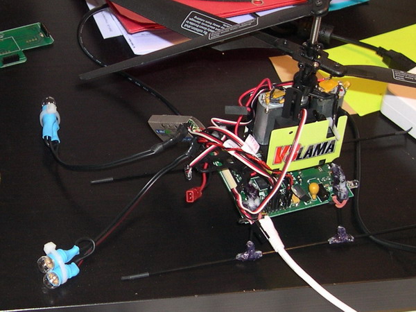
When testing the program, I did not plug the motors. Plugging the motors in this situation is not necessary, and potentially dangerous because of the blades spinning at high speed. Therefore, I use 8V lights (2x4V in series) instead of the motors. With this, I can easily see the variations of the power sent to the motors, without any instrument.
2) External power supply :
I use an external power supply. This is a good idea during development. The batteries discharge rapidly, and recharges slowly.
I don't use a "laboratory power supply", because they are too much expensive, and too large for such power. I use a power supply that looks like a laptop power supply. This can deliver more than 50W at 10V. But unfortunately, the power cable that comes from this power supply is too rigid, and disturbs the UAV during flights. Therefore, I added a silicon cable instead of this rigid cable.
But this power supplies are not good when powering systems that work with impulsions, like motor control on model helicopters. I tested, and I noticed that this induces large unwanted oscillations of the voltage, at maximum power. Therefore, I put 2 big capacitors at the output of the power supply (2 x 4700µF). This totally solves the problem.
3) Matlab – algorithm tests :
When I tuned and programmed the "observer" part of the algorithm, I used Matlab a lot. I interfaced Matlab with my UAV via the bluetooth serial link with the help of the "Psycho-Toolbox".
I can send or receive information from Matlab to the UAV. But I cannot make "real time" transfers with that. I cannot make a control loop inside Matlab for example, because the transfer time is too big: almost 100ms.
Matlab was very useful for testing mathematic formulas. Matlab can also be used to visualize rapidly the results, without large code. I can make complex calculation (Matrix multiplication) very easily. I can also display 3D objects quite easily.
In this project, I wanted to find the good formulas by myself, without to "copy-paste" code or formulas from other projects, or from books. Therefore, Matlab was very useful to feel confident, and understand the mathematic formulas necessary to this project.
Once I obtained a good result on Matlab, I transferred all the mathematic formulas and code to the onboard microcontroller which is programmed in C#. In C#, I cannot make matrix manipulation like in Matlab. Therefore, I had to explicit the calculation first. That is why Matlab was quite useful.
4) Matlab – analyze :
I also used Matlab for displaying the results. I displayed the curbs, vectors for acceleration or magnetic field, 2D or 3D representations. This is very convenient for understanding the behavior of the UAV.
5) Video Recording:
As mentioned before, I was not able to manually control the UAV and simultaneously look at the PC screen to read the parameters in real time.
Therefore, I first used CAMSTUDIO that enables to make video screen captures. I film my UAV with a webcam, and display a Matlab window next to the webcam window. Camstudio records the 2 windows.
This is very clever for analyzing rapidly after the flight.
For a better rendering, I use a camescope and make a video as post-processing. This unfortunately takes a long time, and cannot be used very often.
6) RAM log files:
Sending data to the PC can be done in real time, but this is quite slow because of the limited bandwidth of the Bluetooth link. Therefore, I only send data 5 times per second. This is not enough for analyzing the behavior of the program. I need to have data recorded at the same frequency as the main loop : 20 Hz. This is essential for tuning all the parameters. I think that tuning without any visualization is almost impossible.
Therefore, I programmed something simple : I just record the needed parameters in real time to the UAV RAM. The motherboard has a lot of RAM : 8Mo. I can select the parameters that I need to record.
I then transfer these Logs to the PC via the bluetooth link. This transfer is only enabled when the power to the motors is cut. The sending of these log data is triggered directly via Matlab.
7) 1D Simulation :
I think that it is impossible to tune the PID from zero. Therefore, I first determine a set of PID gains with the help of simulations. I just uses 3 simple "one dimension" simulations that are totally independent.
Altitude (Z) simulation depending on throttle channel.
Yaw simulation depending on yaw channel
Longitudinal (or lateral) simulation depending on the cyclic pitch (or roll) channel
For identifying parameters of this simple simulation, I use log files. For identifying parameters, it is better to make big steps in the joystick position. This is the best way to understand the behavior of a system, and identify the simulation parameters.
In those simulations, I can introduce delay and noise. This is essential to test the robustness of the control loop. Without it, the PID gains would have been set to much higher values... that cannot work at all.
Once the simulation is quite representative (no need to be perfect), I then test it with a PID. The PID gains and parameters (saturation) are first tuned on the simulation. But this is only a "first tuning". This will not work directly on the UAV. But this is a good start!
8) Partial "autopilot":
Of course, the 4 PID cannot be tuned at the same time. The PID cannot directly control the 4 channels when not tuned. Therefore, I have to tune the PID one by one. In my program, I am able to set autopilot to 1, 2, 3, or 4 of the 4 channels. The other channels remain with manual control. This is how I progressively tuned the PIDs:
First, yaw control loop
Then altitude control loop
Finally longitudinal and lateral control loops
9) Live parameters modification:
Tuning all the parameters takes a lot of time. Therefore, I didn't wanted to waste time always compiling, downloading the new program, and reboot the motherboard.
I can easily modify one parameter via the bluetooth serial link. I just send the name of the variable, and the new value. The motherboard displays the answer. For safety reasons, this is only enabled when the motor power is cut. Once again, this function can be made directly via Matlab. Matlab saves the set of parameters, and displays it on the curves for example.